
NEMA Wiring Schematic Manual for Electrical Specialists
About 70% of electrical breakdowns in facilities are due to poor wiring techniques. Such data emphasizes the need of complying with established protocols, highlighting NEMA wiring schematics’ importance for electrical experts. Through these diagrams, wiring setups that satisfy both operational productivity and highest security criteria are presented.
The aim of this guide is to equip electrical professionals with profound knowledge into NEMA criteria. Emphasizing the significance of correct electrical installations is vital. By learning these principles, specialists can significantly minimize the likelihood of hazards and confirm they adhere to safety standards endorsed by Installation Parts Supply. Understanding of l 14 30 plug is vital whether designing new setups or servicing current ones, as it improves the ability to deliver secure and trustworthy electrical solutions.
Major Highlights
- NEMA wiring diagrams are essential for maintaining electrical security and compliance.
- Adequate wiring methods can minimize electrical issues considerably.
- Grasping NEMA norms enhances the efficiency of electrical arrangements.
- Installation Parts Supply encourages adherence to safety protocols in electrical tasks.
- NEMA schematics accommodate a variety of functions across various fields.
Understanding NEMA Criteria and Why They Matter
NEMA norms are essential in the electrical domain, steering safety and performance meticulously. Developed by the National Electrical Manufacturers Association, they establish critical benchmarks for developing, evaluating, and identifying electrical appliances. It ensures standardization and trustworthiness across all electrical configurations, which is priceless.
What Are NEMA Norms?
NEMA categories vary from classes 1 through 13. Every level delineates the conditions required for electrical apparatus to function efficiently. Such as, NEMA 1 offers basic indoor security but is missing dust protection. Alternatively, NEMA 4 ensures equipment is sealed, a requirement for withstanding significant water exposure. Grasping these classifications is key in picking proper equipment.
How NEMA Standards Matter for Electrical Protection
The impact of NEMA norms in ensuring electrical safety is significant. They play a significant part in minimizing electric shock, apparatus breakdowns, and fire hazards. Proper adherence to NEMA classifications empowers equipment to perform securely under certain surrounding conditions. For outdoor application, NEMA 3 classifications deliver protection against the elements, guarding the equipment from inclement climate like precipitation and snowfall. In regions at risk of explosions, classifications such as NEMA 7, 8, and 9 are critical for ensuring security.
Uses of NEMA Standards in Wiring Schematics
The use of NEMA criteria in wiring drawings is vital for protected, optimal electrical systems. These diagrams utilize consistent symbols and formats derived from NEMA ratings, streamlining the interpretation of detailed electrical configurations. This standardizing is helpful. It encourages lucidity, uniformity, and minimizes errors, thus improving electrical security across residential and factory sectors.
NEMA Wiring Diagram Fundamentals
NEMA wiring diagrams are crucial for electrical experts, rendering intricate connections transparent. They describe the connections and elements in diverse installations. By comprehending the components, categories, and notations of NEMA diagrams, professionals can enhance their performance in deployments and upkeep.
Components of NEMA Wiring Schematics
NEMA drawings comprise key components for particular electrical configurations. You’ll find wiring terminals, connectors, and various hardware for safe connections. Each piece ensures energy is distributed effectively, in accordance with security standards.
Varieties of NEMA Wiring Schematics
NEMA utilizes different drawings, like connection blueprints and electrical designs. Schematics outline equipment interconnections, while designs show power flow. Selecting the right schematic aids in troubleshooting and deployment.
Typical Notations Used in NEMA Wiring Schematics
Notations in wiring drawings are crucial for unambiguous conveyance. They represent controls, loops, and couplers. Knowing these icons assists teams read schematics correctly. Thus, it guarantees configurations adhere to NEMA norms.
NEMA Wiring Diagram Characteristics
For electrical experts, grasping the key components of detailed electrical wiring diagrams is vital. These schematics bring both clarity and wholeness, aligning installations with NEMA norms. They necessitate precise annotation and sizing to reduce installation errors. This encourages a safer and optimal workplace.
Primary Attributes of Correct Electrical Wiring Schematics
Precise electrical wiring schematics are vital in electrical undertakings. They embody important qualities such as:
- Transparency: Diagrams are required to be simple, reducing the risk of misinterpretation.
- Wholeness: They need to contain all essential parts, connections, and electrical ratings.
- Standard Compliance: Following NEMA standards is mandatory for guaranteeing security and operation.
- Detailed Labeling: Unambiguous labels on each component are fundamental for grasping and minimizing errors.
- Correct Scaling: The proportions should mirror the real setup to depict the system correctly.
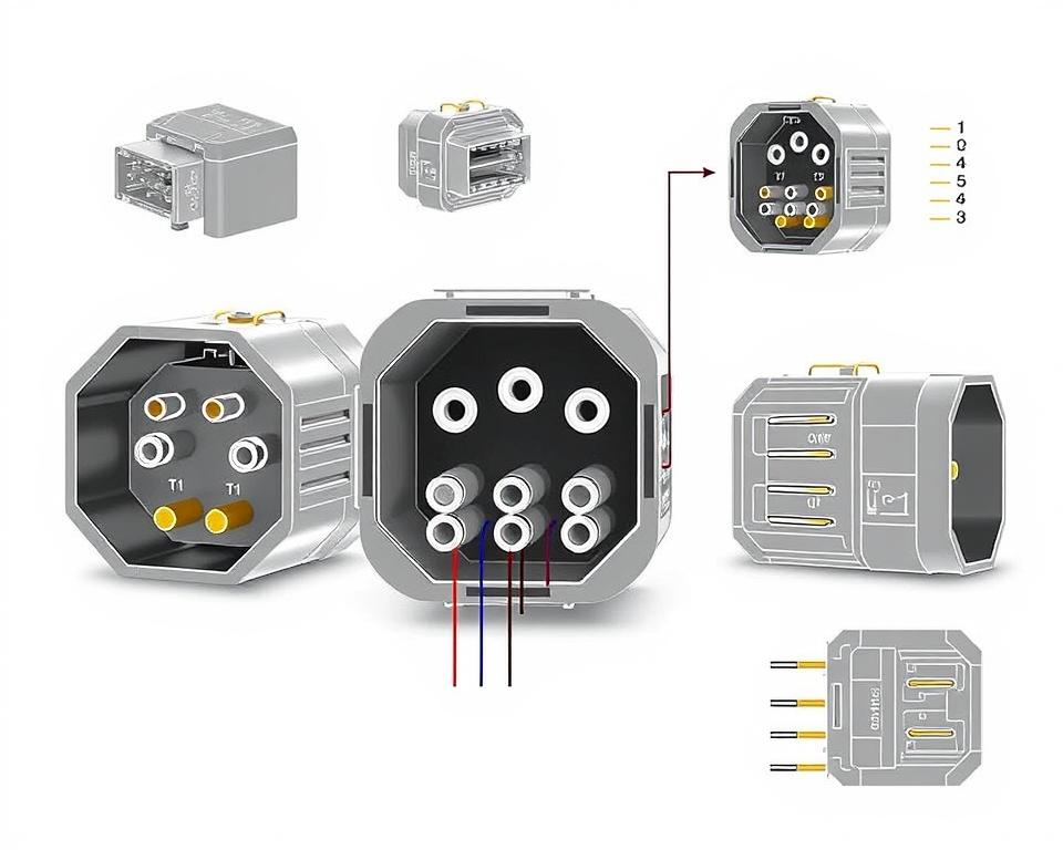
Grasping NEMA Coupler Layout
Understanding of NEMA coupler pinout is vital for establishing accurate linkages in electrical setups. Knowledge about specific pin arrangements ensures safety and equipment functionality. There is a diversity of NEMA connectors, crafted for different power levels and amperages, including:
| Connector Model | Amperage Rating | Power Rating |
|---|---|---|
| L5-15 | 15A | 125V |
| L5-20 | 20A | 125V |
| L14-20 | 20A | 125/250V |
| L1430C | 30A | 125/250V |
| L620C | 20A | 250V |
| L1430C | 30A | 125/250V |
| L630R | 30A | 250V |
Comprehending NEMA connector pinouts is vital for reliable junctions, enhancing efficiency. It’s imperative to align interfaces with devices accurately using locking or straight blade variants, to dodge dangers.
NEMA Appliance Wiring
NEMA device wiring covers diverse configurations for safe electrical appliance linkages. These rules ensure that appliances work together securely, minimizing danger. Knowing the various NEMA equipment and their wiring is essential for electricians.
Various Kinds of NEMA Devices
NEMA organizes units by category based on power levels and amperage demands. Primary arrangements are:
- 2-Pole 2-Wire
- 2-Pole 3-Wire Grounding
- 3-Pole 3-Wire
- 3-Pole, 4-Wire with Grounding
- 4-Pole 4-Wire
- 4-Pole 5-Wire Grounding
These configurations are employed in domestic settings and factories, handling 125V, 208V, and 480V.
NEMA Outlet Wiring Outlined
NEMA plug wiring changes to meet diverse energy requirements, with locking types ensuring consistent connections in unstable environments. For example, the L5-15 plug works at 15 amps, common in enterprise settings, whereas the L14-20 is intended for 20 A at 125/250 V.
The NEMA naming scheme helps in selecting the right plugs, emphasizing characteristics like polarity and connection to ground. Such accuracy guarantees that appliances function safely.
NEMA Outlet Wiring Guidelines
Proper wiring of NEMA sockets aligns with electrical standards and safety norms. For instance, L530R receptacles are configured for 30 amps at 125 V, with L630R options for 250 voltage. Correct grounding is vital to dodge electrical accidents.
Selecting accredited NEMA plugs and receptacles ensures safe, standard-compliant setups. It’s critical to check official protocols when installing.
NEMA Motor Wiring and Implementations
NEMA motor wiring is essential in electrical engineering, notably for industrial use. Knowing how NEMA motor configuration works secures that motors are set up for best performance. Motors, like one-phase and three-phase models, need proper wiring to function reliably and effectively.
Introduction of NEMA Motor Wiring
Understanding NEMA motor wiring demands understanding of connections and arrangements. Most three-phase motors offer dual-voltage, signifying they can work on both low (208-230V) and high voltage (460V). High voltage wiring allows motors to draw less current than at low voltage. High voltage perks comprise thinner cables for the input, a significant benefit for engines over 10 HP.
While both NEMA and IEC devices are used in the sector, NEMA models are usually larger and more expensive than IEC ones for less than 100 HP applications. NEMA controllers vary from size 00 to 9, fit for various uses. A common characteristic in NEMA trips is a Trip Class of 20, intended to trip when a motor’s draw surpasses 6x the Full Load Amperage (FLA) in 10 s.
Selecting the Right NEMA Motor Arrangement
Selecting the correct NEMA motor setup influences overall efficiency and safety. A standard three-wire control circuit employs three wires for a on/off pushbutton station, facilitating simple motor management. Typical three-phase setups comprise the 12 Lead Dual Voltage and 6 Lead, enabling Wye and Delta connections.
IEC motor starters often include phase failure detection, boosting safety. They also include modifiable Trip Classes for tailored protection in low voltage levels operations. Moreover, many units have heat protection, vital for single-phase and Dual Voltage configurations.
| Arrangement | Power Type | Amperage | Usual Function |
|---|---|---|---|
| 12 Lead Dual Voltage | Dual Voltage (208-230V / 460V) | Varies by motor size | Applications with Wye Start and Delta Run |
| 6 Lead | Single or Dual Voltage | Maximum 32A | Both Wye and Delta arrangements |
| Single Phase | One Voltage | Ranges from 1 to 5 amps | Two Speed, Two Winding applications |
| Delta Connection | High-Power Voltage | Depending on setup | Used for Current Transformers and various setups |
The Final Word
Understanding NEMA wiring diagrams and standards is crucial for electrical experts aiming to boost their expertise and adhere to electrical safety standards. These principles not only ensure protected and efficient electrical configurations but also avoid dangers stemming from improper wiring. As mentioned, following NEMA norms leads to the augmented performance of various NEMA units and configurations.
For electrical professionals, the availability of high-quality resources can significantly impact the success of their tasks. Installation Parts Supply offers a extensive selection of wiring products meeting NEMA criteria. This empowers professionals to obtain critical components for fulfilling these significant regulations. Superior resources and deep knowledge of NEMA wiring drawings substantially improve installation security and effectiveness.
Throughout electrical installations, always place safety and accuracy as a priority. Mastering NEMA norms offers the knowledge required to applying industry standards correctly. This guarantees that every electrical link established conforms to premium norms.
Frequently Asked Questions
Identify NEMA wiring drawings?
NEMA wiring drawings display the configurations and connections of NEMA-standard electrical devices. They comply with safety and operational standards established by the National Electrical Manufacturers Association.
How are NEMA criteria crucial for electrical protection?
NEMA norms are essential to setting safety and operational benchmarks for electrical equipment. These standards help electrical specialists minimize electrocution risks, equipment failure, and burn dangers.
Which elements are essential in a NEMA wiring schematic?
Essential components in a NEMA wiring drawing include circuit configurations and junction blueprints. These diagrams also include thorough markings and depict the electrical system’s diverse parts precisely for setups.
What types of NEMA wiring drawings exist?
Diverse NEMA wiring drawings address diverse needs, including circuitry for power distribution and connector schematics. Each design serves a specific role in electrical installations.
Identify the common symbols used in NEMA wiring diagrams?
Typical symbols in these schematics represent switches, fuses, outlets, and more. Utilization of these symbols facilitates clear interaction and accurate analysis of wiring drawings.
What are the key characteristics of accurate electrical wiring drawings?
Accuracy in electrical wiring drawings is defined by their clarity, comprehensiveness, and detailed annotation. They need to meet NEMA criteria to avoid faults in installation.
Explain a NEMA connector pinout?
A NEMA connector pinout outlines electrical connections at a connector, indicating specific pin assignments. This ensures secure and effective junctions in electrical systems.
Which are the various kinds of NEMA devices?
NEMA appliances consist of various electrical receptacles and interfaces, like adapters and sockets. They are crafted for different amperage and voltage requirements to meet specific application requirements.
In what way is NEMA plug wiring set up?
NEMA plug wiring is determined by specific current and voltage needs, following security protocols and electrical codes for diverse electrical applications.
Which standards are there for NEMA outlet wiring?
Recommendations for connecting NEMA outlets underline complying with electrical regulations, securing correct charge alignment, and choosing proper gauge sizes. This ensures both security and functionality in electrical configurations.
Describe how to wire a NEMA motor effectively?
To set up a NEMA motor, one must grasp its specific one-phase or tri-phase arrangement. Choosing the right wiring approach is vital, along with practicing electrical protection for optimized motor efficiency.
What should I consider when opting for a NEMA motor setup?
Choosing a NEMA motor configuration requires an evaluation of the system’s voltage and current demands and operational characteristics. It’s also crucial to ensure compatibility with pre-existing systems for reliable efficiency and security.